NPTEL Digital System Design Week 11 Assignment Answers 2025
1. In the state diagram given in figure 1 which of the states could be clubbed to reduce the number of states?
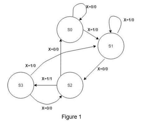
- S0 and S1
- S1 and S2
- S1 and S3
- S0 and S2
- S0 and S3
- None of the above
Answer :- For Answers Click Here
2. Identify the states which are equivalent
- a ,b
- b, d
- e, g
- d, a
- b, g
Answer :-
3. what will be the total number of states in the final reduced state diagram.
Answer :-
4. Given the state diagram, select the state table that represents the diagram without any state reduction (i.e., use the normal state table as is).
.png)
.png)
.png)
.png)
Answer :-
5. Based on the state table selected in Question 4, use the implication table method to minimize the number of states. What is the valid initial lower triangular representation of the state table?
.png)
.png)
.png)
.png)
Answer :-
6. After applying all the steps of the Implication Table method, which of the following statements are correct?
- c, e are equivalent
- h, f are equivalent
- d, g are equivalent
- e, a are equivalent
- a, c are equivalent
Answer :-
7. After completing all the steps of the Implication Table method, how many distinct states will be left?
Answer :- For Answers Click Here
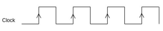
8. Given the waveform, determine the state of Register A and Register B in the format xxxxxxxx,xxxxxxxx, where each “x” can be either 0 or 1. Assume that the input to Register B is 0. Provide the values of Register A and Register B, respectively, without any space between the two values, and separated by a comma.
Answer :-
9. Suppose we need to perform the addition a+b+c, where each of a, b, and c is an 8-bit number.
Ignore the number of cycles required to load the initial operand (e.g., a) into Register B.
Assume that Register A is initially set to 0 (reset state).
How many cycles will be required to perform the addition a+b+c?
Answer :-
10. what will be the values of SL and SH, Cout respectively after first clock cycle
- 0x34BDEE5, 0x00000000, 1
- 0x34BDEF5, 0x00000000, 0
- 0x34BDEE5, 0x00000000, 0
- 0x34BDEE5, 0x000AB000, 1
Answer :-
11. what will be the total number of cycles required to perform addition of two 64 bits numbers using above architecture, ignoring additional details you need to use the details provided?
Answer :-
12. A 128-bit adder is designed using 32-bit adders with a multi-cycle approach. The total design includes the following components:
The 32-bit adder has a delay of 20 units for the addition operation.
There are 5 registers between the stages, each having:
Setup time of 0.8 units,
Hold time of 0.3 units,
Propagation time of 0.6 units.
The carry propagation delay for each 32-bit adder is 2 units for each bit of carry, meaning the carry delay for a 32-bit adder is 64 units in total.
The 128-bit adder works by splitting the 128-bit input into 4 chunks of 32 bits, each processed by one 32-bit adder. The multi-cycle approach assumes sequential addition, where each stage’s result is stored in a register before proceeding to the next stage. The carry-out from the previous stage is passed to the carry-in of the next stage.
Given this information, calculate the total time required to perform the 128-bit addition.
- 88 units
- 106.8 units
- 112 units
- 114.6 units
- 120 units
- 345.2 units.
- none of the above
Answer :-
13. A 128-bit adder uses 32-bit adders with a multi-cycle approach. The carry propagation delay for each 32-bit adder is 64 units for each stage. If the total carry propagation delay across all 4 stages is given by the sum of the carry propagation delays for each stage, calculate the total carry propagation delay for the entire 128-bit addition process.
- 64 units
- 128 units
- 192 units
- 256 units
- 384 units
Answer :-
14. The 128-bit adder uses 5 registers in total. Each register has a setup time of 0.8 units, a hold time of 0.3 units, and a propagation time of 0.6 units. Assuming the setup and hold time delays are cumulative and affect the transition between each stage, calculate the total time spent in register delays during the 128-bit addition.
- 1.6 units
- 3.2 units
- 4 units
- 4.8 units
- 5.2 units
Answer :-
15. If the carry propagation delay is completely neglected, calculate the total time required to perform the 128-bit addition, considering only the adder delays and the register setup times. (approx)
- 84.8 units
- 106.8 units
- 120.8 units
- 128.8 units
- 160 unit
Answers :- For Answers Click Here